This tutorial should give some initial understanding about IRIG 106 chapter 10 recording files and some other chapters of IRIG 106 related to it.
The tutorial was created by Data Bus Tools, a German company developing software to process IRIG 106 chapter 10 files or live streams. Data Bus Tools actively participates in the development of the IRIG 106 standard.
A free version of the FLIDAS software can be used to see most of the low level IRIG 106 chapter 10 file information and learn about the standard. Of course the software does more and has commercial versions as well.
Data Bus Tools is a software company and the focus of the tutorial will be information technology aspects and no other issues like the physical transmission of data via radio etc.
Throughout the tutorial there might be additional information hidden until you click at the ►. You can safely skip it if you are not interested in more details.
Whenever this tutorial talks about CH10 it is short for IRIG 106 chapter 10.
Why is IRIG 106 chapter 10 relevant?
Which organizations are involved with IRIG 106?
IRIG 106 deals with topics like:
Recordings can capture complex data from different sources in parallel. E.g.

This chapter gives some information on PCM which is closely related to IRIG 106 chapter 10. You could skip the information though and continue with the recoding format section.
PCM streams can be transmitted from the aircraft to a ground station for immediate inspection of the data and / or stored on a recorder on aircraft for later inspection.
It was the primary recording method in the past where magnetic tape recorders were used.
PCM is described in IRIG 106 Chapter 4.
The PCM stream is a continuous stream of 0 and 1 representing the samples.

The image shows the values of two sensors (red and blue curve) over time. They are sampled at equidistant points in time and the measurements are digitalized (e.g. 9 instead of 9.3333333). The samples of both sensors are then multiplexed and put to a binary bit stream.
When this bit stream is received from a radio link you need to know where it starts to locate the measurands:

The image shows a PCM stream on top. The red bits are the periodically repeating frame syncs that indicate the start of a minor frame. The blue blocks are complete minor frames.
After a minor frame lock is achieved the bit stream can be broken down into single minor frames in the lines below. Once this is done the position of the measurements can be calculated and the data can be split into PCM words.
To offer lower frequency minor frames can contain a subframe ID which sequentially numbers the minor frames.
A sequence of minor frames of each subframe ID is called a major frame.
| Sync | Subframe ID | Word 2 | Word 3 | Word 4 | Word 5 | |
|---|---|---|---|---|---|---|
| 1 | Major frame | |||||
| 2 | ||||||
| 1 |
Sampling measurands with higher frequency is called supercommutation. They appear in several PCM words of the same minor frame. See the green words in the table below.
Sampling measurands with lower frequency is called subcommutation. They only appear in one PCM word and not in every minor frame but only in minor frames with specific subframe ID. See the blue word in the table below.
| Sync | Subframe ID | Word 2 | Word 3 | Word 4 | Word 5 |
|---|---|---|---|---|---|
| 1 | |||||
| 2 |
Commutation is the distribution of measurements over the PCM words. Decommutation is the process of reconstructing the measurements from the PCM stream.
Data of different sources called channels are multiplexed into a stream of data. They have a data type like:
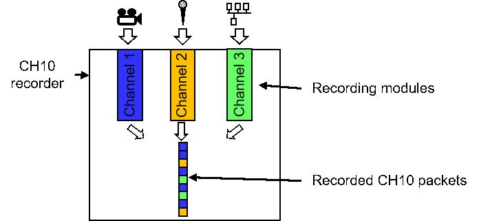
In principle a CH10 recorder works as shown in this picture. It shows a recorder that records video, audio and a digital data bus on three channels.

The incoming data is encoded into CH10 format in the recording modules.
When a slice of the data of one channel is encoded, the recording hardware for the channel enqueues this packet in a sequence of packets. This sequence of packets is recorded and / or published on a network.
Data of each channel is collected into a packet.
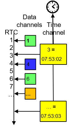
Packets do not directly contain a time stamp. Instead there is a 10 MHz real time counter (RTC). You see it in the left of the image counting upwards.
Each packet notes the RTC value at the point in time where it was created. You can see that in the colored blocks in the image.
A special time channel records a time source like from a GPS receiver.
The packets of the time channel (yellow blocks in the image) refer to an RTC value and an absolute time as well. The time of other RTC values (and hence other packets) can be interpolated then.

Time channels must record a time reference at least once a second.
Every CH10 file must start with a packet describing the configuration of the recorder.
The next section will explain more on TMATS.
Before looking at other IRIG 106 chapters, the most important things to remember on chapter 10:
The configuration of an FTI system is described with the telemetry attribute system (TMATS).
TMATS can describe different aspects of the FTI. Recorders are just one type.
TMATS is described in IRIG 106 chapter 9.
TMATS organizes the configuration in several groups. Here some more important ones:
A simple attribute definition in ASCII TMATS may look like this:
G\PN:Flight testing of new Aircraft;
The line consists of several codes separated by "\".
A more complex line in ASCII TMATS may look like this:
Now we have an index on one of the codes. There may be none, one or several indices on each of the codes.
R-1\TK1-11:51;

			R-1\ASR-11:12800000;

R-1\AMN-11-1:Video;
R-1\ADL-11-1:8;
R-1\AMSK-11-1:FW;
R-1\AMTO-11-1:M;
R-1\ASF-11-1:0;
R-1\ASBW-11-1:5120000;
IRIG 106 chapter 10 requires that these commands can at least be issued on RS232/RS422 and using discrete lines.
Recorders may additionally use Ethernet, Fibre Channel or IEEE 1394b for commands.
Recorders must provide the recorded data for download using Fibre Channel or IEEE 1394b and optionally also Ethernet.
The Telemetering Standards Coordination Committee (TSCC) allows participation in the standard: www.tscc.org
| Abbreviation | Meaning |
|---|---|
| ASCII | American Standard Code for Information Interchange |
| CH10 | Chapter 10 (of IRIG 106) |
| DoD | Department of Defense |
| FLIDAS | Flight Data Studio |
| FTI | Flight Test Instrumentation |
| IRIG | Inter Range Instrumentation Group |
| PCM | Pulse Code Modulation |
| RCC | Range Commanders Council |
| RTC | Real Time Counter |
| TSCC | Telemetering Standards Coordination Committee |
| TMATS | Telemetry Attributes Transfer Standard |
| XML | Extensible Markup Language |